
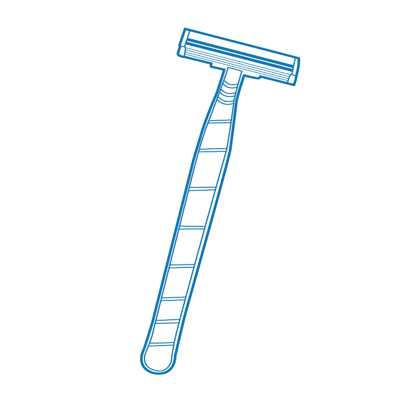
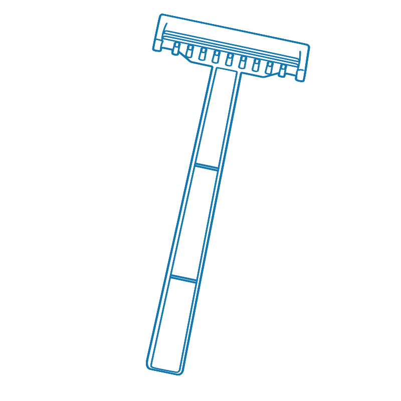
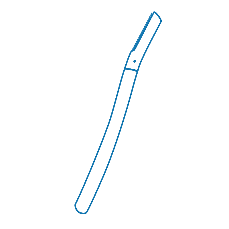
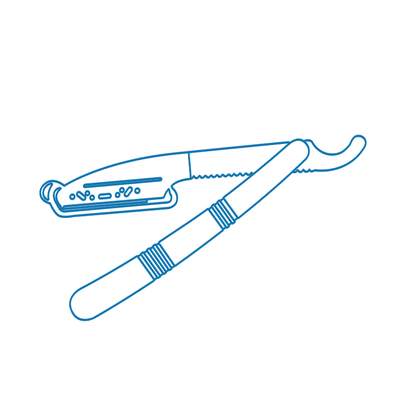

A razor handle can look correct in an approval sample yet develop a rough seam during production. A protective cap may leave the mold incomplete, while a cartridge frame appears straight until it cools and no longer assembles correctly. These differences create sorting work, inconsistent presentation, and questions about product fit. Changing machine settings without identifying the cause can move the problem elsewhere: more packing may reduce a sink mark while creating flash. The practical solution is to connect each visible defect with its location, cavity, material, and processing history. A structured review of razor injection molding defects helps the Manufacturer and buyer agree on corrective trials, measurable acceptance criteria, and a repeatable process for handles, caps, and cartridge components.
Effective control of razor injection molding defects combines cavity-level inspection, confirmed resin preparation, controlled filling and packing, balanced cooling, and drawing-specific acceptance. For Haward OEM and ODM projects, approve both component appearance and assembled function, with traceable samples and documented process changes.
The following guide helps molding engineers, QA managers, and sourcing teams connect visible defects with practical checks. It covers Haward handle, protective-cap, and cartridge-component applications, then explains how controlled trials and clear inspection records support Customizable products without treating every appearance difference as the same technical problem during production reviews.
Map the Defect to Its Location and Function
Use a Shared Inspection Language
Start by identifying the feature that changed. A thin ridge at a parting line, an unfinished cap corner, and a shallow depression above a handle rib require different investigations. Photograph the location, record the cavity number, and compare it with the approved drawing and reference sample.
| Visible Defect | Razor Application | Measurement or Check | First Investigation |
|---|---|---|---|
| Flash | Handle seam or cap edge | Projection height and extent, mm | Shut-off fit, wear, cavity pressure |
| Short shot | Cap latch or cartridge rib | Feature completeness; part mass, g | Gate restriction, venting, delivered shot |
| Warpage | Cartridge frame or handle connector | Profile deviation, mm; assembly fit | Cooling balance, shrinkage, ejection |
| Sink mark | Handle surface above a thick junction | Depression depth, mm; visual comparison | Wall thickness, packing, gate freeze |
This matrix defines investigation routes, not pass limits. The Supplier should distinguish decorative surfaces from grip areas, cap-retention features, and blade-supporting geometry. That distinction keeps molded razor quality connected to the component’s actual purpose.
Trace Razor Handle Flash to Sealing and Pressure Conditions
Check the Mold Before Increasing Clamp Force
Razor handle flash is excess plastic that escapes through an unintended mold gap. It can appear along a handle seam, around an ejector location, or at the boundary of an overmolded grip. A normal parting-line witness is not automatically flash; compare the projection with the approved surface requirement.
Autodesk’s flash troubleshooting guidance identifies worn or poorly fitted tooling, insufficient clamping, overpacking, and unsuitable venting among possible causes.
- Inspect shut-off surfaces for damage, contamination, and localized wear.
- Compare affected cavities to distinguish a local tool issue from a process-wide change.
- Review fill-to-pack transfer, pressure peaks, melt condition, and clamp capability.
- Check vent dimensions against the resin and tool specifications.
A recurring ridge at one location suggests a different investigation from flash appearing across every cavity after a setting change. Confirm the cause before adjusting pressure. If trimming is proposed, approve the method and reinspect for sharp remnants, loose particles, and altered fit.
Diagnose Short Shots Through Filling and Venting
Confirm That Every Functional Feature Is Complete
A short shot occurs when plastic fails to complete the intended cavity shape. On a razor, the missing area may be a small cap latch, a narrow cartridge rib, or the end of a handle texture. Overall appearance can seem acceptable while a functional detail remains incomplete.
Autodesk’s short-shot guidance connects incomplete filling with flow restrictions, trapped air, insufficient material delivery, temperature, and machine condition.
- Confirm material feed, delivered shot, and repeatability of the screw cushion.
- Inspect the nozzle, runner, and gate for restrictions.
- Check venting near the last areas to fill.
- Run a controlled fill study to compare the filling sequence across cavities.
- Adjust speed or temperature within the resin’s approved processing window.
The Manufacturer should verify completion with feature inspection, not part weight alone. A heavier part can still contain an incomplete latch if other areas are overpacked. For an OEM cap, confirm both the full latch geometry and the specified retention function after correction.

Measure Cartridge Warpage After Controlled Cooling
Separate Molded Shape from Fixture-Induced Shape
Cartridge warpage can shift assembly datums, change cap fit, or distort the relationship between supporting features. The cause may involve uneven cooling, uneven shrinkage, packing distribution, or deformation during ejection. An apparently flat part under heavy clamping can become distorted again when released.
Autodesk explains how temperature differences across a component contribute to warpage. For razor components, translate that principle into a repeatable measurement method:
- Measure against defined datums with consistent support and contact force.
- Specify the time after molding and the measurement environment.
- Record coolant flow and inlet/outlet temperatures for relevant circuits.
- Inspect blocked cooling paths, unequal ejection, and handling before the part stiffens.
- Check both free-state geometry and the specified assembled condition.
Longer cooling may help, but the investigation should also address local temperature differences and wall geometry. For a Customizable ODM handle, changing rib layout or adding a decorative mass can alter shrinkage behavior. Recheck the connector and assembly fit after such changes.

Reduce Sink Marks by Checking Thickness and Packing
Investigate the Material Beneath the Surface
Sink marks are local surface depressions often found opposite ribs, bosses, or thick junctions. A glossy razor handle can make a shallow depression highly visible. Color and texture affect its appearance, so a single depth measurement does not fully define cosmetic acceptance.
Autodesk’s sink-mark guidance links the defect to localized shrinkage and insufficient compensation during cooling.
- Compare the affected area with the approved wall-thickness and rib design.
- Check whether packing pressure reaches the thick section before the flow path freezes.
- Review hold time, gate restriction, and material delivery stability.
- Assess geometry changes when a thick junction cannot be packed consistently.
Increasing pressure should be a controlled trial because other features may become overpacked. Persistent depressions near a load-bearing connector may justify sectioning or other investigation for internal voids. A decorative texture can change visibility, but any design revision still needs approval. The Supplier should compare appearance under agreed lighting and retain signed limit samples.
Match Drying and Material Handling to the Actual Grade
Avoid One Drying Recipe for Every Handle and Grip
Material preparation belongs in the investigation of razor injection molding defects, but drying is not a universal remedy for flash, short shots, warpage, or sinks. Confirm the exact resin grade before changing the dryer settings.
For example, Avient’s TPE processing guidance distinguishes products that normally need no drying from hygroscopic grades that require it. It directs processors to individual technical data sheets for temperature and time.
- Record the resin grade, lot, color masterbatch, and approved material blend.
- Where required, verify drying temperature, duration, and residual moisture.
- Check dryer performance and protect prepared material from moisture pickup.
- Keep regrind use within the approved specification and processing validation.
- Investigate contamination or material changes when defects follow a batch change.
For Haward molded handles and grip components, the appropriate controls depend on the selected material system. A Customizable color or material option should retain traceable preparation records so the OEM or ODM team can compare results meaningfully.
Use Controlled Trials to Confirm the Corrective Action
Compare Results Without Confounding the Variables
Record the original process, state a hypothesis, and change a defined variable. For a gate-seal study, compare part mass at different hold times; RJG describes this method and the use of cavity-pressure evidence when small parts make weighing difficult.
The following hypothetical trial uses one cavity and five stabilized shots per setting. Hold pressure, filling conditions, material, mold temperature, and total in-mold time remain constant. Values illustrate the method; they are not Haward test results or acceptance limits.
| Trial | Hold Time | Mean Part Mass | Mean Sink Depth |
|---|---|---|---|
| A | 4 s | 8.42 g | 0.18 mm |
| B | 6 s | 8.50 g | 0.06 mm |
| C | 8 s | 8.50 g | 0.06 mm |
The plateau suggests little further benefit from extending hold time in this example. Review individual results and measurement uncertainty before confirming gate seal. Then repeat across cavities and assess flash, dimensions, and assembly. Five shots support diagnosis here; they do not establish production capability or a lot-release sampling plan.
Turn Improvements into Drawing-Specific Production Controls
Link Cosmetic Approval with Functional Acceptance
Molded razor quality requires measurable requirements and consistent inspection conditions. ISO 20457:2026 provides a framework for tolerances and acceptance conditions for plastic molded parts. It does not assign one permissible flash height or warpage value to every razor.
For each approved component, define:
- Critical features: connector datums, cap latches, blade-supporting areas, and accessible edges.
- Measurement rules: instrument, support, conditioning, and drawing-specific limits.
- Appearance rules: viewing conditions and approved boundary samples.
- Sampling points: startup, restart, material changes, and scheduled cavity checks.
- Reaction plan: identify and segregate affected output, investigate, and authorize restart.
Retain the approved process window, tool-maintenance history, and cavity-level results. Revalidate relevant features after gate repairs, vent modifications, material changes, or cooling-system work. Trend recurring razor handle flash and cartridge warpage by cavity to guide maintenance. This gives the buyer and Manufacturer a practical basis for repeat-order consistency and keeps engineering improvements connected to the released specification.
Build a Clear Molding Specification for Your Next Razor Project
Send Haward your component drawings, defect photographs, material requirements, and target quantities. Discuss a Customizable OEM or ODM program with defined inspection points and acceptance criteria, so razor injection molding defects can be addressed through evidence and controlled improvement.